- Vidya Nagar, Bhopal, Madhya Pradesh
- GST NO. : 23AADCL3954C1ZV
- +91-8889017888
100 Piece (MOQ)
| Business Type | Manufacturer, Exporter, Supplier, Trader, Distributor |
| Brand Name | ETEILY |
| Condition | New |
| Application | Electrical Adaptor, Electronic Adaptor |
| Click to view more | |
Preferred Buyer From
| Location | Worldwide |
Product Details
Certification
CE Certified, ISI Certified
Type
Internal Antenna
Impedance
50Ω
Gain
6dBi
SKU
ET-5GPC-5L10CP26-U
Product
Antenna
Technology
5G
Radiation
Omnidirectional
Dimension
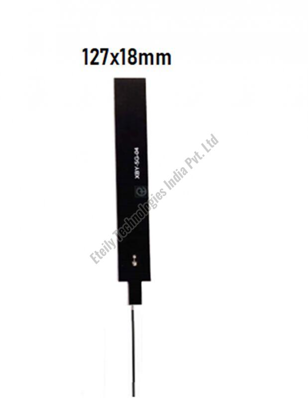
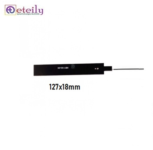
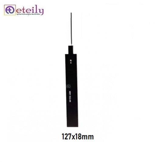
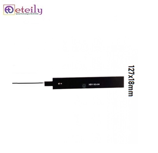
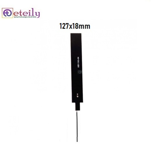
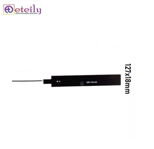
127x18mm
Cable
1.13mm
Connector
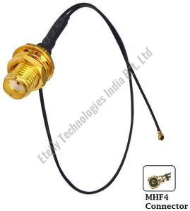
UFL Right Angled
Product Code
ET-5GPC-5L10CP26-U
Payment Terms
L/C, D/A, D/P, T/T
Delivery Time
5 Days
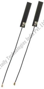
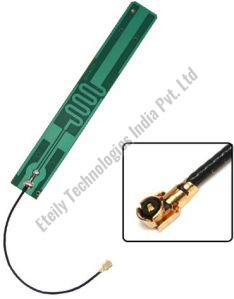
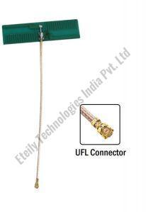
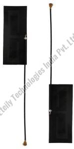
Using a 5G internal PCB antenna with a 1.13mm cable and a U.FL (or IPEX) connector involves several components and considerations to ensure optimal performance and integration within your device. Here’s a breakdown of what you need to know:
Components and Specifications-
Antenna:
- Type: Depending on your application, the antenna could be a monopole, dipole, patch, or another type suitable for 5G frequencies. Ensure it’s designed to handle both sub-6 GHz and potentially mmWave frequencies if needed.
- Integration: The antenna needs to be designed for optimal placement on the PCB to minimize interference and maximize signal performance.
-
1.13mm Cable:
- Cable Type: The 1.13mm cable is a type of coaxial cable commonly used in RF applications due to its small size and low loss. It’s suitable for connecting antennas to the main PCB but might not support extremely high frequencies as well as other cable types (e.g., 0.81mm or 0.6mm cables).
- Length: The length of 10 cm (L-10CM) should be managed carefully to avoid excessive signal loss or reflection, especially at higher frequencies. Cable length and routing can impact signal integrity.
-
U.FL Connector:
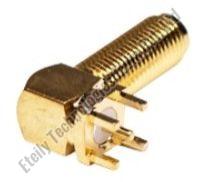
- Connector Type: U.FL connectors are compact RF connectors used for connecting antennas to PCBs. They are commonly used in small devices and are suitable for frequencies up to several GHz, which makes them suitable for 5G applications.
- Installation: Ensure proper soldering of the U.FL connector to the PCB to avoid connection issues. The connector needs to be aligned precisely with the antenna cable for reliable performance.
Looking for "Best 5G Internal PCB Antenna with 1.13mm Cable ( L-10CM ) + UFL Connector" ?
Piece

